 HOMOKINETIC JOINTS – ancestor of the constant velocity joint (simultaneous), that is, transmitting the rotational movement from shaft to shaft in a uniform manner, there are a pair of closely spaced universal joints, and in the extreme case, two such joints joined together. However, this solution is still burdened with disadvantages, related to the requirements of the correct operation of the cardan system. Among other things, the Tract joint is known, essentially a Cardanic joint, but composed of slidingly cooperating elements of properly made planes. Such a joint allows an exceptionally large deviation of the axis of the mating shafts, even up to 50 degrees. Another solution is the Garrington joint, made of two hollow hemispheres, cooperating with each other through radially arranged sliders. Ball joints became an extension of this idea, allowing the shafts to be tilted in any direction – without limits, resulting from the definition of the planes of rotation (swings) individual parts.
The principle of operation of such a joint is as follows: the driving torque is transmitted by large bearing balls arranged in appropriate grooves, made in the housing of the device. These grooves allow the balls to move freely around the circles, whose common center marks the intersection of the axes of both shafts. The movement of the balls is made in the planes passing through the shaft axis. In any relative position of the two shafts a plane, which all the balls make up, divides the angle between the driven and driving shafts in half. As a result, the angular speeds of both shafts are always the same. In practice, during each rotation of the tilted shafts, said balls roll back and forth in each of the grooves, in which they are embedded. Given, that they simultaneously transmit driving torque through the short contact line with the grooves, you can imagine, how serious implementation difficulties (accuracy) and material entails making such a joint. Hence, years ago, front-wheel drive joints were burdened with low durability – the manufacturers did not recommend rapid acceleration, when the wheels are tightly turned. These limitations contributed to not the best opinion of the front drive.
One of the first ball joint solutions was the Weiss joint, in which two identical dishes were used, cooperating by means of four spheres placed in the grooves. The fifth ball, central, it positioned both parts of the joint axially.
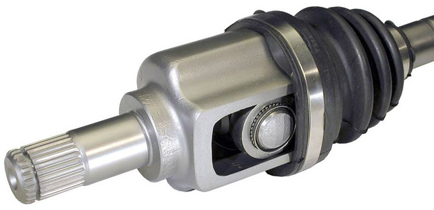
A certain mutation of the ball joint is commonly used today, known as the Rzepp joint (according to some Birfield sources). This device only consists of a housing, the inner part (in which the second section of the shaft is embedded), basket and six balls. Due to the simple structure, mass production and durability of the Rzeppa joints are widely available. Designers only need to determine the axle load on a new car and select the appropriate joint from the catalog. The durability of these devices is very long and the only problem is to ensure long-term tightness of the cover, under which there is a special lubricant, most often with the addition of molybdenum disulfide.
Because the Rzepp joint itself does not allow the shaft length to be adjusted, The "other side" of the driveshaft of a front-wheel drive car must be equipped with a joint that enables such correction. Let us note, that we face much less requirements on the part of the differential, when it comes to the torsion angle of both shafts. Some variations of ball joints are used here, allowing slight longitudinal movement or three-finger joints. A triple cross with arms ending with ball sections with bearings, transmitting driving torque, simultaneously move freely along the grooves inside the housing.
CV joints
Visited 1,122 times, 1 visit(s) today