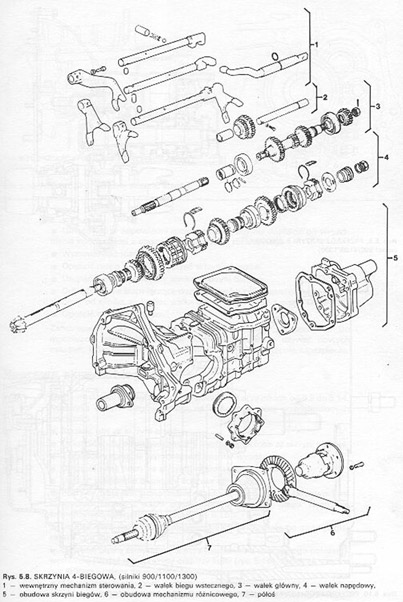
 The components of the 5-speed gearbox are shown in the illustration. The disassembly of the gearbox consists in the following steps.
■ Drain the gearbox oil.
■ Unscrew the screws of the rubber covers and remove the driveshafts from the gearbox.
■ Remove the release bearing from the clutch housing.
■ Unscrew the rear gearbox cover and remove the gasket.
■ Remove the snap rings from the ends of both shafts.
■ The rear cover is also the housing for the wheels 5. running. Use a suitable puller to remove the synchronizer hub from the shaft 5. running. Then remove the gears 5. running
■ Remove the two large circlips on the outside of both ball bearings.
■ Unscrew the closing plate of the slider locator mechanism and remove the three springs and the three balls. One of the springs is shorter and belongs to the reverse runner.
■ To detach the clutch housing, unscrew the nuts on the outside of the housing and the three nuts on the inside of the clutch housing.
■ Grip the clutch housing, remove the gearbox housing from the shafts and sliders.
■ Remove the reverse shaft, which is held in place by a nut and a retaining plate (Lynx. 5.17). Lift the shaft up, until the plate can be lifted on the stud and remove the plate.
■ Remove the screws from the forks.
■ Remove the slides.
■ Pull the reverse gear stick upwards, until it comes out of the socket.
■ Remove the reverse fork together with the pinion.
■ Remove the outer track stick 1/2 running, after unscrewing the selector screws.
■ Pull out the center pointing stick 3/4 running. It is provided with a locking pin.
■ The other two locking pins are located in the walls between the slots of the guides. They will fall out when the gearbox is tilted.
■ Place the forks and selector back onto the levers as quickly as possible, so that they are not changed during assembly.
■ To remove the main and drive shafts, grasp the gears of both shafts at the same time and take them out together.
■ From the inside of the clutch housing, undo the cover screws and remove the cover.
■ Remove the final drive.
■ Remove both nuts on the gearshaft flange.
■ Pull out the shaft with rubber bellows and seal rings. Note the position of these rings.
■ Undo the screws securing the release bearing hub.
■ Pull out the hub together with the main shaft bearing. There should be no difficulties with this, because the bearing is not tightly seated in the seat.
■ Remove the drive shaft bearing from the housing, which is also loose and should not require the use of a puller. However, if we use a puller, this should be careful, so that the plug does not slide out of the hole.
■ Remove the gears from the drive shaft. If the sleeves were too tight on the shaft, can / can be done, that you will have to press the shaft out of the wheels. In this situation, the gear 1. the gear should be well supported under the press. Dismantle the wheels one by one.
■ The synchronizer is disassembled in the following order.
– In the case of a synchronizer 3/4 gear, remove the snap ring with special pliers. After removing the split ring, visually inspect both spring rings and stones.
– In the case of a synchronizer 1/2 gear, remove the springs on both sides of the hub. Mark the hub and coupling sleeve on one side with a scribe and press the hub out of the sleeve. Verify all gears. Bearings must not turn noisy or have excessive lateral play. Similarly check the condition of the wheel bushings on the drive shaft. In addition, check the wear and play of the splines on the shaft for the synchronizer hubs.
The gearbox is assembled in the reverse order. Please observe the following instructions.
■ Components of a synchronizer 3/4 running. The protrusion of the snap ring must fit into the stone cutout. Press the locking ring into the seat and insert the snap ring into the groove, using special tongs.
■ By folding the synchroniser 1/2 put the stones on the gear, put the spring on one side and turn the synchronizer. Slip the sleeve onto the hub in accordance with the marked marking and insert the second ring. Place the second spring in this way, that the ends of both springs are displaced by 120 °.
■ Install the shift shaft seal rings.
■ Bevelled edge of the synchronizer coupling sleeve 1 /2 gear must be opposite the phase of the reverse wheel.
■ In a synchronizer 5. gear, the hub is provided with a lubrication groove, which must face the wheel during assembly 5. running.
■ To install the lock washers under the drive shaft snap ring, use a piece of pipe and a long bolt, which screws into the shaft journal. Place the two washers with the convex side outwards and slide them onto the shaft. Place the snap ring on the shaft. as close to the washers as possible, then put on the pipe and screw in the screw. By tightening the screw, the spring washers are compressed and the snap ring is displaced. Watch from the side, when the ring is aligned with the groove, and then knock it in with the small pin. To check, that the ring has settled in the groove all the way around before the screw is removed. The washers are mounted with great pressure, what causes, that there is no play between the shaft gears.
■ The large snap ring only fits on the outer side of the bearing in one position.
■ When installing the sliders, do not forget to insert the two locking pins into the holes from the center of the casing and the longer pin into the end of the slider 3/4 running. When inserting the springs and locating balls, pay attention to the sliders, make a shorter spring (marked in green) was on the left side (belongs to reverse gear). The position of the other springs is free.
After all parts are assembled, the preload of the main gear bearings can be adjusted. Put more than one thicker one on the bearing race, but two thinner shims and screw on the adjuster ring and nuts without spring washers. Tighten the nuts gradually around the circumference, that the ring is flush against the housing and presses against the bearing raceway. Use a feeler gauge to measure the distance between the collar of the ring and the housing, paying attention, that it is the same on all sides. If it is not, means, that the ring has been tightened crookedly and the nuts must be loosened again. Tighten the nuts, by setting the same gap around the perimeter.
Remember the thickness of the feeler gauge, inserted with some resistance. Unscrew the ring and use a micrometer to determine the thickness of the shims used. Subtract the thickness of the feeler gauge and the additional ones from the measured value 0,04 mm. The result will be the thickness of the washer, which must now be additionally placed under the bearing raceway from the side of the adjustment ring. Screw on the ring, tightening the nuts with the torque 10 N m. Finally, install the clutch release bearing and prepare the gearbox for installation.
Do not forget to fill the gearbox with the amount of oil 2,4 DM3. Before assembling the gearbox, the parts should be thoroughly checked. You should check, that all gears do not show signs of seizure, cracks or chips. Replace the gear if necessary, remembering to replace the mating pulley at the same time, because they are linked in pairs. Bearings, which are noisy or have too much lateral play when dry, need to be replaced. The drive shaft must not show any signs of wear, and the splines must have sharp edges. Check synchronizers, that their outer surfaces and teeth are not worn or chipped. In doubtful cases, they should be replaced. Replace all seals and sealing rings, because it will be cheaper than dismantling a leaky gearbox again. The main and drive shafts can be clamped between the lathe centers and their runout can be checked, which should not exceed 0.05 mm. The shafts must not be straightened and therefore need to be replaced. To check, the forks are not bent. The sliders must be able to slide easily in their seats in the gearbox. If misfeeds occur, replace the part or correct the defect.
The main gears are not closely related to each other. Therefore, when replacing the drive shaft, it is not necessary to replace the driven wheel, if it is not damaged. Check the wear of the tapered roller bearings and the condition of the bearing raceway in the clutch housing. If necessary, knock the treadmill out of its seat in the housing. Before dismantling the differential, measure the play between the ring gear and the satellites. To do this, hold the crown wheel and rotate one of the satellites in both directions. Only a barely perceptible play is allowed, which can be reduced to give a thicker thrust washer
■ Unscrew the screws on the disk wheel. Thus, the protection of the satellite axes will be removed.
■ Knock out the satellite axis with a suitable mandrel.
■ Remove satellites and ring gears.
Check the condition of the ring gears and their seats, Replace damaged parts. When assembling, pair the ring gear and the satellites and insert them into the housing. Insert the satellite axis and turn it as long as possible, until the shaft hole aligns with the housing hole, then press in the locking pin. Cable driving the cable (cable) the speedometer is inserted with the appropriate pin. A properly selected sleeve must be used to mount a tapered roller bearing, which is attached to the inner treadmill.