Starter repair
After all parts have been washed in gasoline and blown dry, they should be verified. Replace damaged parts.
Brushes
On a DF type starter, pull the springs and brushes out of the brush holder plate to check. The degree of wear of the brushes is determined, comparing their length with the new brushes.
Brushes must be replaced in a set, even as only one has reached its consumption limit. Replacing the brush requires unsoldering the braided wire.
In the DW starter, the entire brush holder is replaced, when the length of the brushes decreased below 8 mm. The brush holder that must be reassembled must be cleaned. If necessary, bend the pressure springs.
commutator
The commutator surface should be smooth, must not have any grooves or burn marks The surface should be wiped with a cloth soaked in tetrachloromethane or light gasoline.
Stronger dirt and deposits can be removed with a fine-grained emery cloth, rotating the impeller slowly.
Clamp the rotor in the lathe and center it accurately. The deviation of the commutator circularity may be maximally 0,03 mm. Keep the commutator sanding permissible, minimum diameter. After treatment, remove the mica between the commutator divisions (e.g. with a ball) to a depth of approx 0,5 mm below the treadmill.
The rotor with the worn commutator must be replaced. A burnt commutator winding indicates a short circuit in the rotor.
Rotor
The rotor is not subject to repair and must be replaced in case of damage.
Breakdown to the rotor mass is checked with alternating current 110 V. One of the sampler's ends should be touched to the package of the rotor plates, and the other one to one of the commutator's divisions.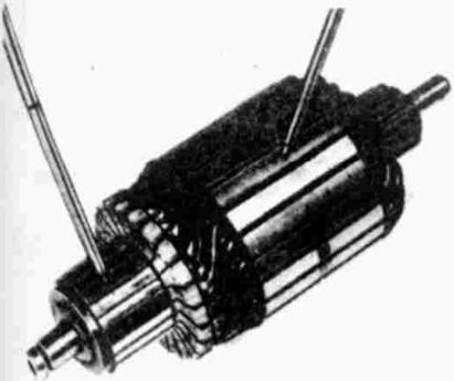 Lighting of the bulb indicates damage to the rotor insulation.
The interturn short circuit of the rotor is checked with an ammeter connected to the battery 2 volt. The tips of the ammeter should be placed against the commutator like this, that there are always two divisions between the measurement points. By checking the following sections, approximate current values should be obtained (the size alone is not authoritative).
Solenoid switch
In order to check, the tester should be connected to the power cable terminal and to the ground. If the tester bulb is not lit, the electromagnetic switch must be replaced.